Reflow Soldering Oven Controller Project
I am currently working on a project for an electronic device that I would like to start selling in the future. I have managed to order ten prototypes from the Chinese company JLCPCB. Unfortunately, after analyzing the costs, I have decided that for the small batches of products I want to sell initially, it would be a better idea to solder the prefabricated PCBs from a supplier (either JLCPCB or a European one in the future) myself. After researching the market for affordable soldering reflow ovens, I have concluded that for a similar price, I could build such an oven (including the controller) myself, allowing me to personally select all the components and parameters according to my own preferences. The concept of a DIY reflow oven controller is not new, so I could easily find plenty of useful information about it on the internet.
List of parts
As this is not a tutorial on how to build a reflow oven system, I am going to present the list of only the most important parts I have used for those who might be interested.
| Type of part | Manufacturer | Part number |
|---|---|---|
| Solid State Relay (SSR) | RELPOL | RSR52-24D25 |
| SSR's Heat Sink | RELPOL | RH21 |
| AC-DC Converter | TDK-LAMBDA | KPSB6-5-E |
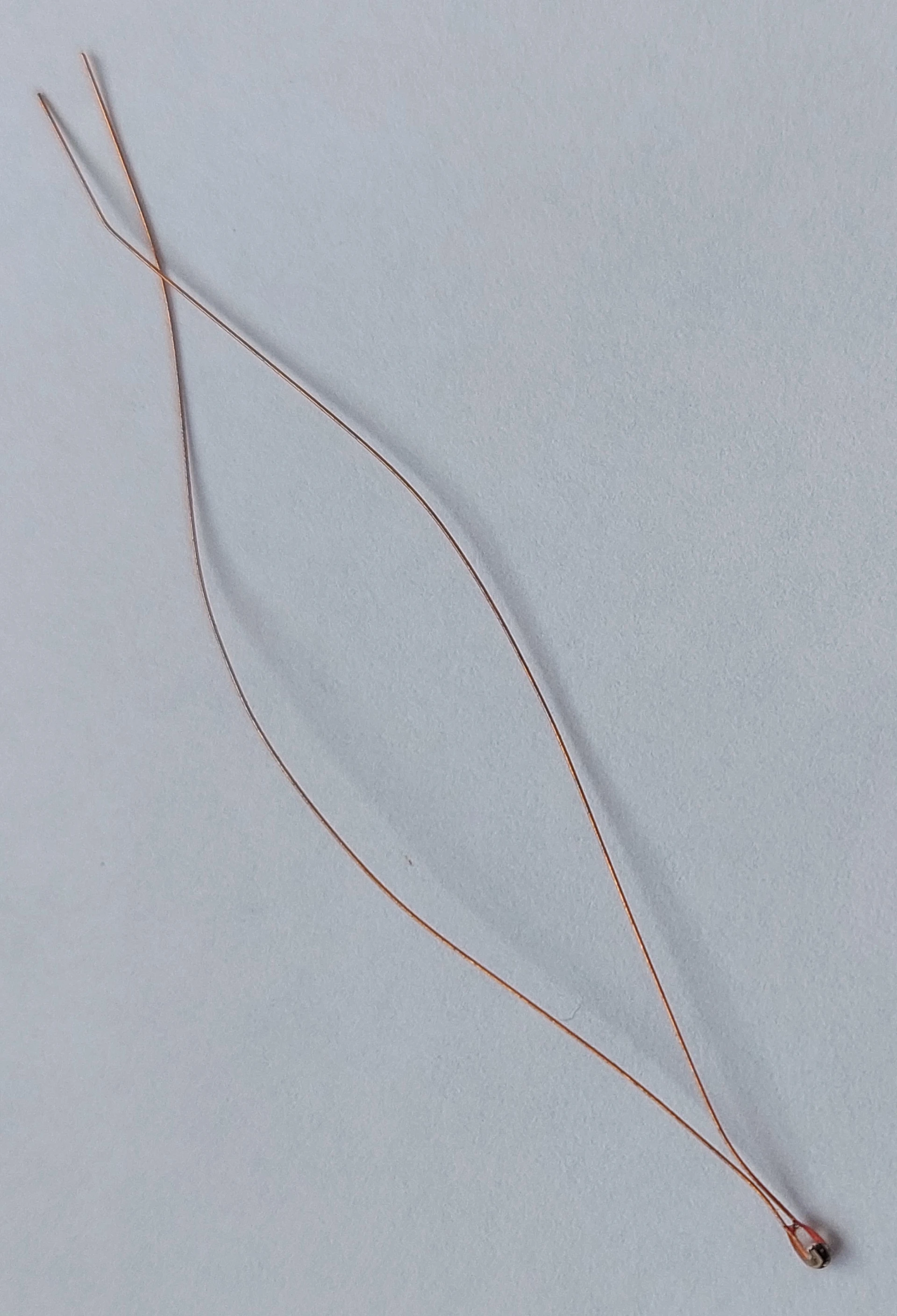
| Thermistor | TEWA TEMPERATURE SENSORS | TT2-100KC3H-7 |
| AC Socket | PCE | 1040-0S |
| AC Socket | SCHURTER | DC11.0001.003 |
| Electric oven | Esperanza | EKO008 |
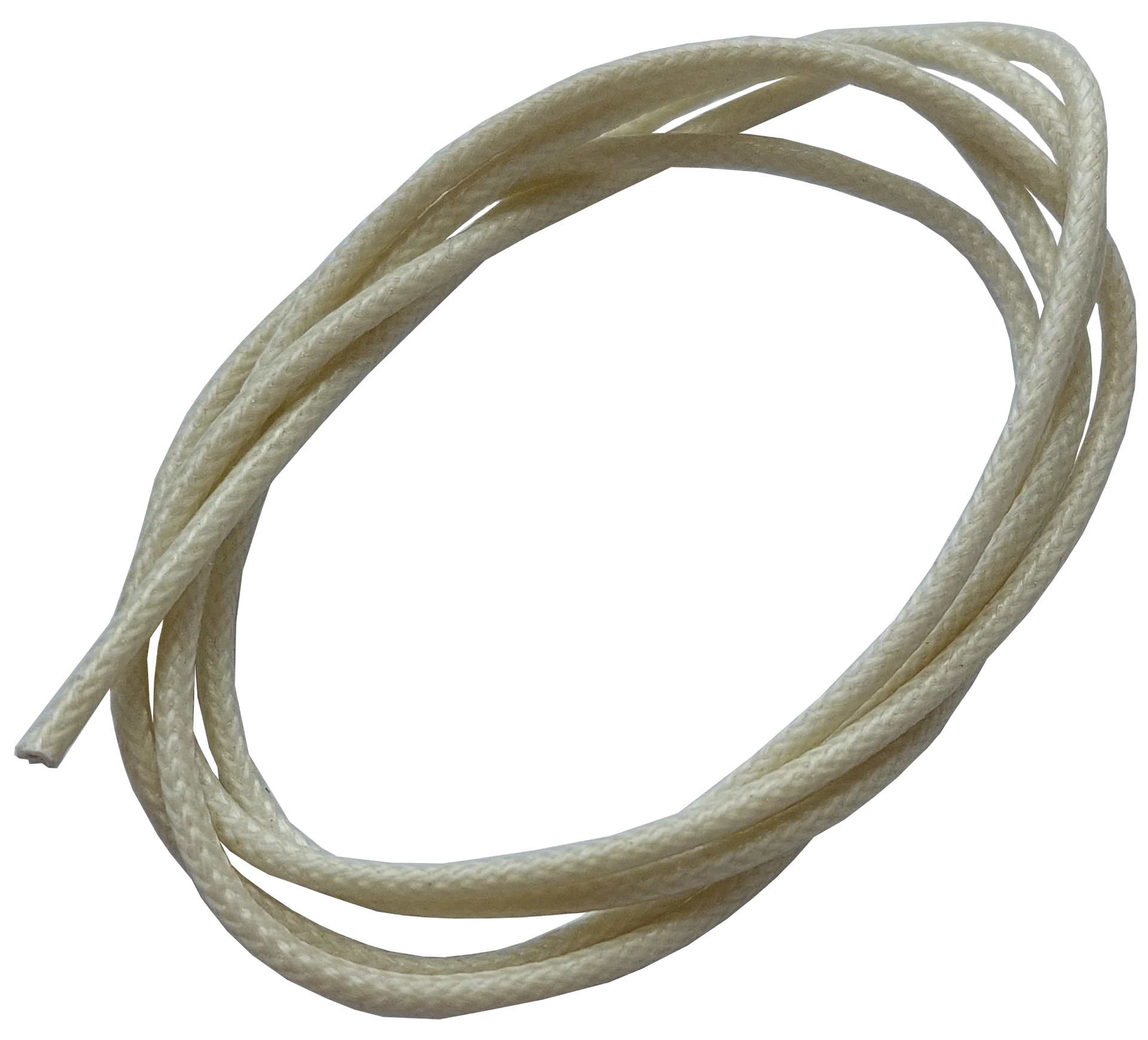
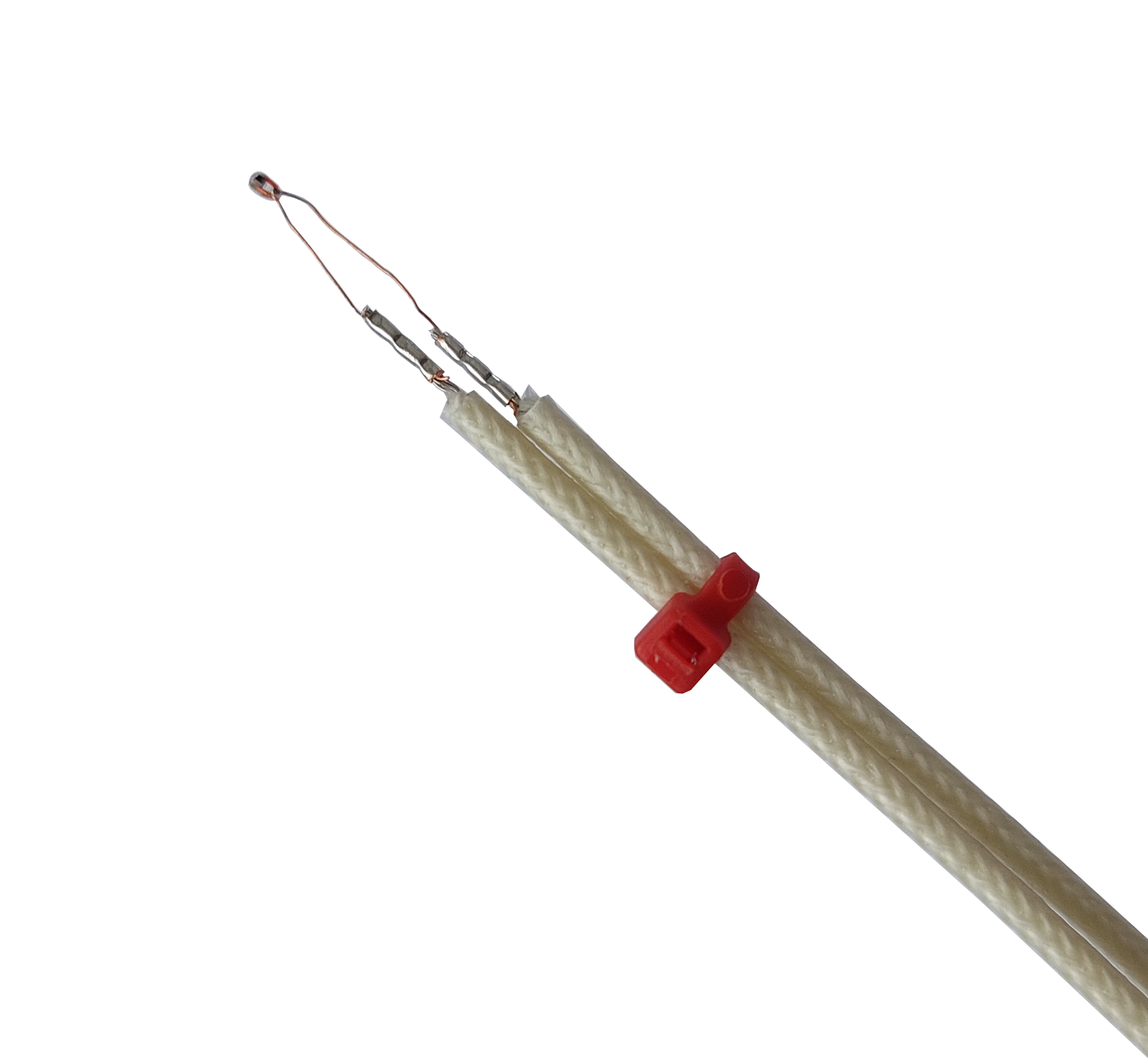
| Heat-resistant Wire | LAPP | 0091350 |
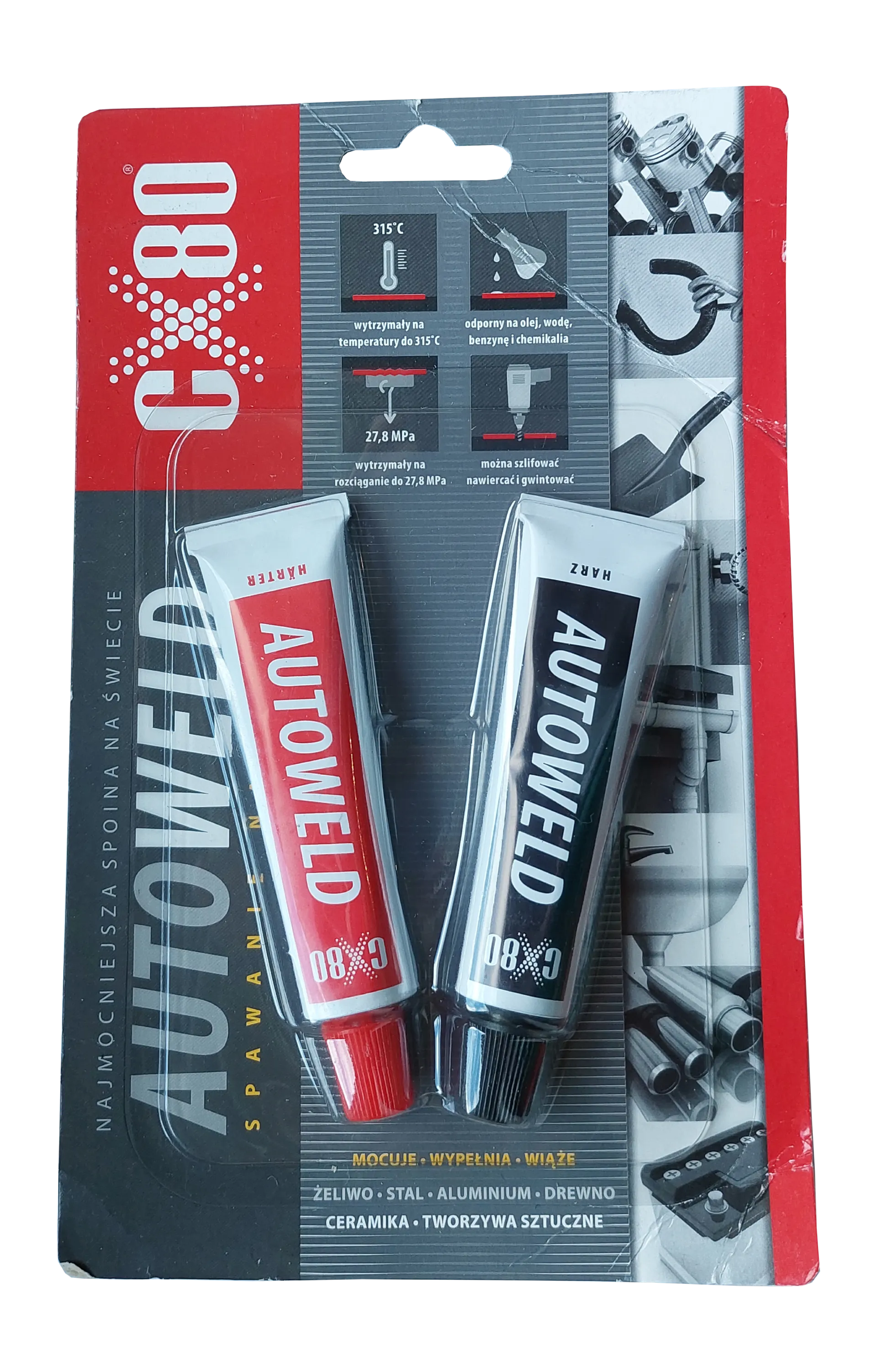
| Heat-resistant Glue | CX-80 | AUTOWELD |
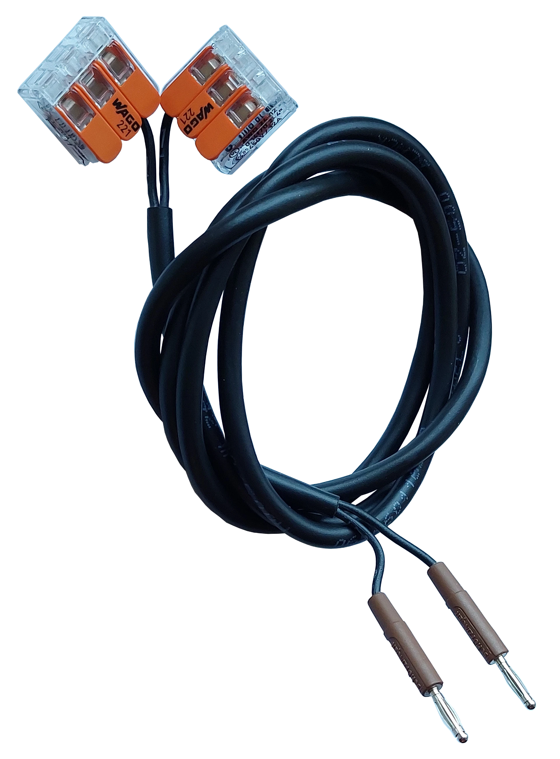
| PCB Terminal | WAGO | 236-401 |
| Banana plug | SCHÜTZINGER | FK 02 L NI / BR |
| Banana socket | SCHÜTZINGER | SEB 3400 NI / SW |
| USB-A Socket | MOLEX | 48258-0002 |
| Development Board | RASPBERRY PI | PICO W |
| Universal Board | ROTH ELEKTRONIK GMBH | RE200-LF |
| Isolated connectors | BM GROUP | - |
| Case | KRADEX | Z1 |
| TFT LCD Display | Waveshare | 17344 |
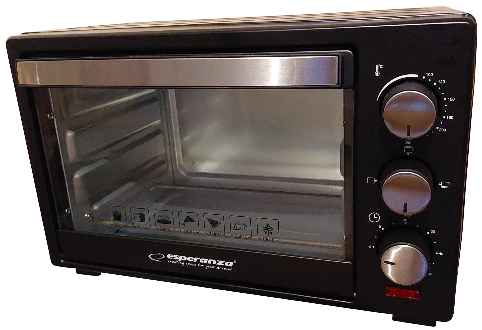
Electric oven choice
I spent some time searching for a suitable oven capable of following the soldering profiles for various solder pastes and decided to choose the Esperanza EKO008 model. During my search, I primarily focused on the maximum temperature, which, from my observations, should be around 250 °C to maintain a safety margin while soldering with higher-temperature pastes. This oven has four heaters, which is an additional benefit because four heaters help spread heat more evenly than if there were only two (at least that is what I believe).
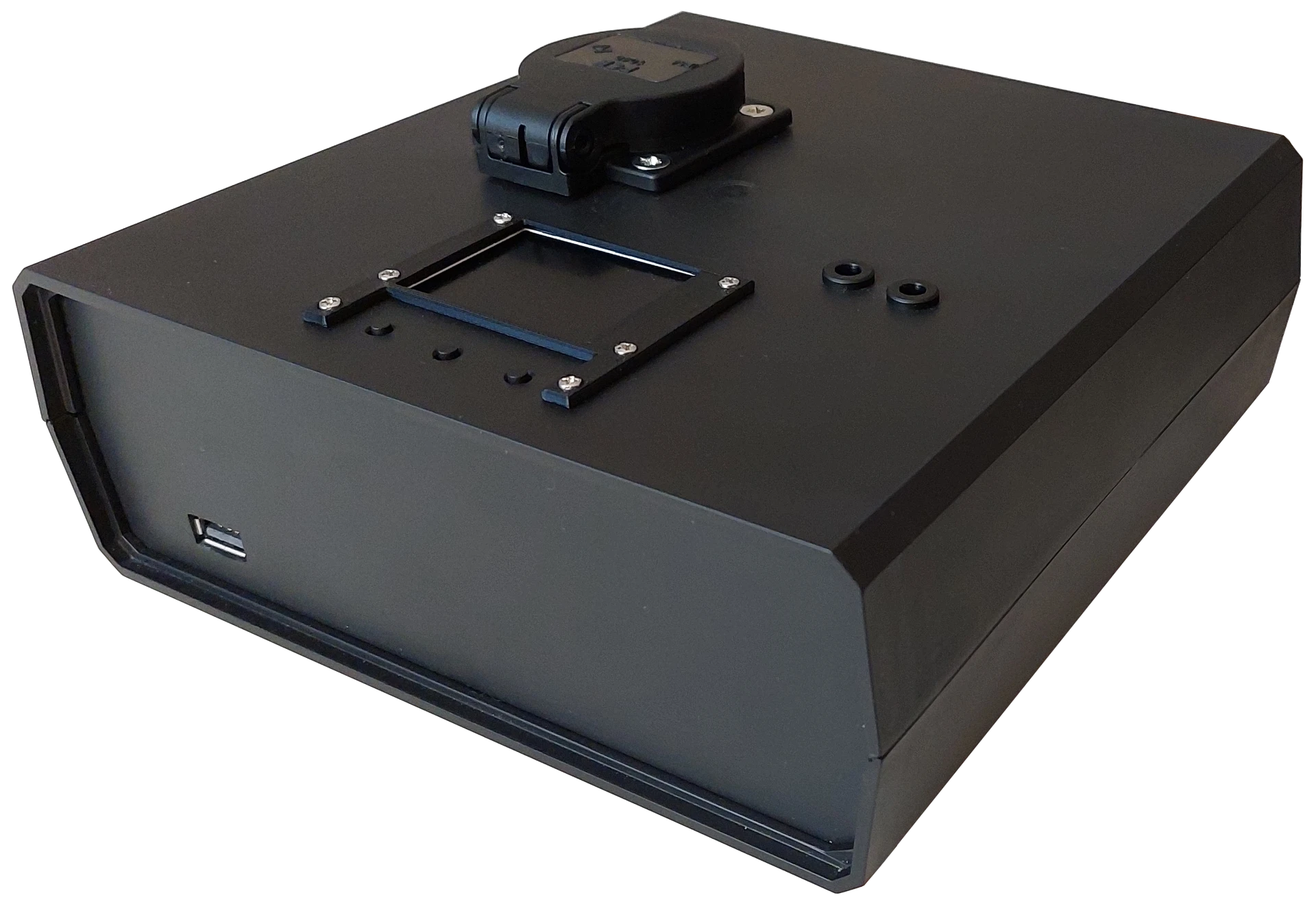
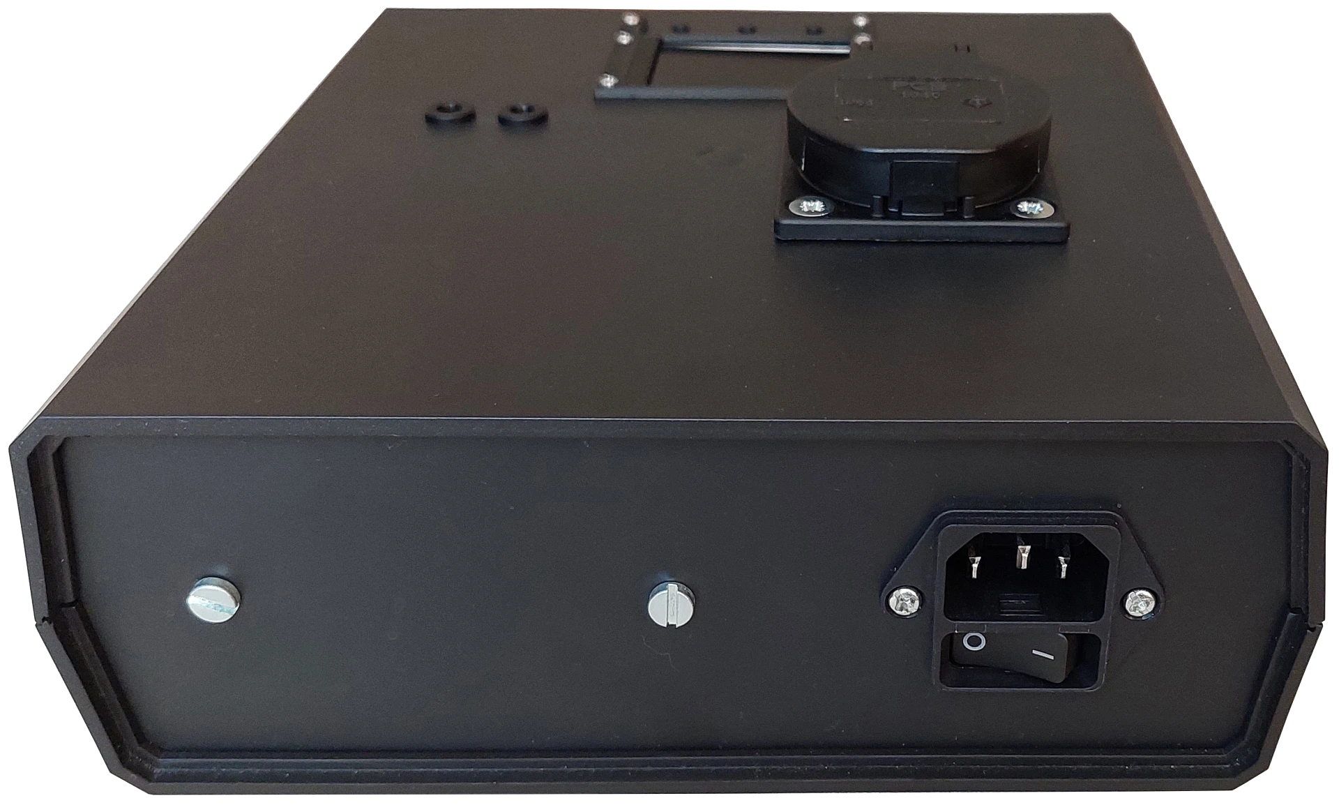
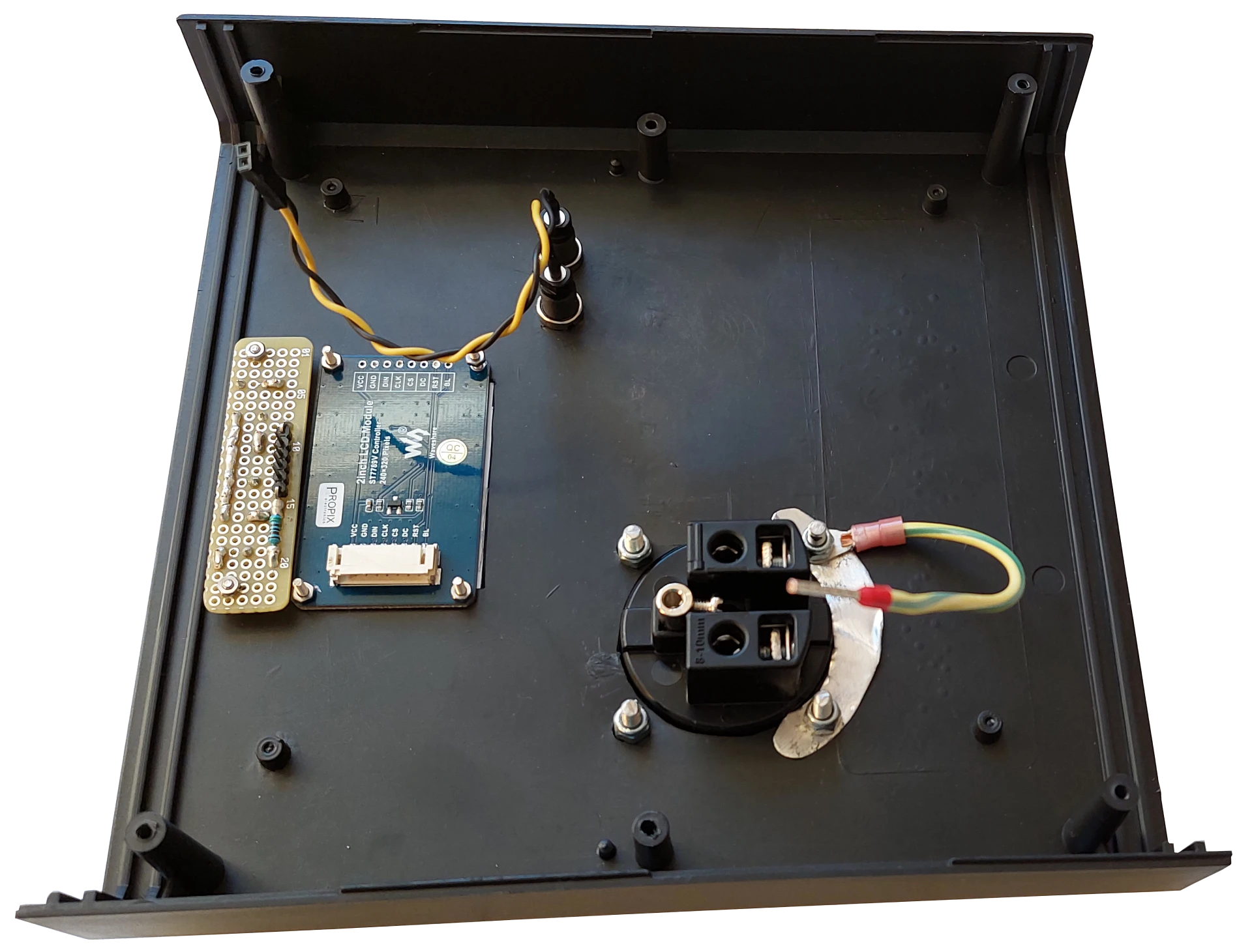
Controller assembly
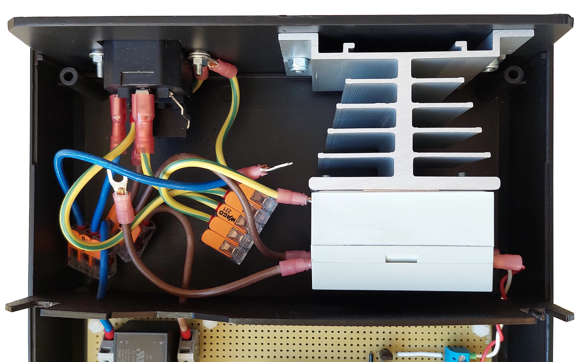
Let's dive into the most interesting part of this project: the controller build. I have had the black polystyrene case lying around on my shelf for some time and decided that it would be perfectly suitable for the project. The case perfectly fits all of the components needed and allows me to divide it with the 3D printed ABS separator into two sections: AC and DC, which improves the electrical safety of the device. The second, and basically the last part that I had in my supplies, was the TFT LCD display that I had been playing around with in the past, and I thought it would also be good enough for this project. Among the purchased parts, the noteworthy one is the Solid State Relay (SSR), manufactured by a Polish company called RELPOL, which is a breath of fresh air after seeing the same Chinese one in every other project of this type. I did not cut corners on this build; almost everything was bought from reputable manufacturers. Going back to the relay, it is capable of withstanding 25 amps of continuous current, the switching voltage range is 4 to 32 volts DC, and I chose the zero crossing version to avoid any Electromagnetic Interference (EMI). I have mounted the relay on a heatsink, and after a couple of tests I have conducted so far, there are no signs of overheating. In fact, I do not see any significant temperature rise just by touching the case, so this passive cooling solution should be sufficient.
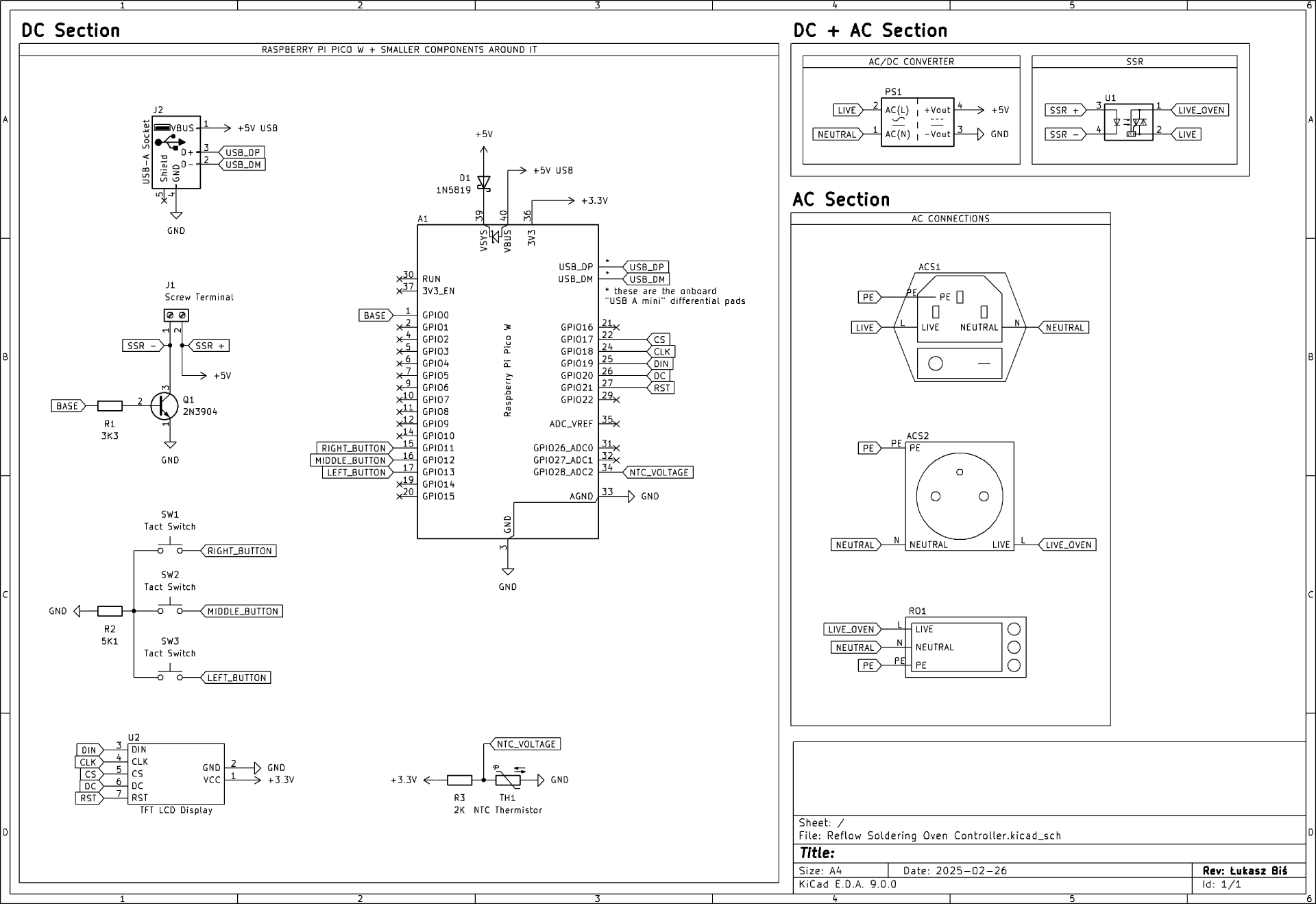
I have described the AC section in the previous paragraph; now it is time for the DC part. I chose the 5-volt AC-DC converter to power the DC electronics. To safely connect the live and neutral lines to the converter, I decided to try a very clever PCB terminal from WAGO, the 236-401. It holds the wires very securely in its case, so there is a limited chance of any shorts, especially with the other safety measures I implemented to make the device safe, such as high-quality isolated connectors, a 3D-printed separator, and polyamide screwed spacer sleeves to mount the PCB to the case. After the voltage is converted to 5 volts, it powers the Raspberry Pi Pico W. I have chosen this development board for the following reasons:
- Wi-Fi (controlling the device wirelessly and/or sending data during soldering to archieve each soldering batch),
- Bodmer's TFT_eSPI library for the TFT LCD display supports RP2040 microcontroller present on the PICO W board,
- ease of programming it in the Arduino IDE.
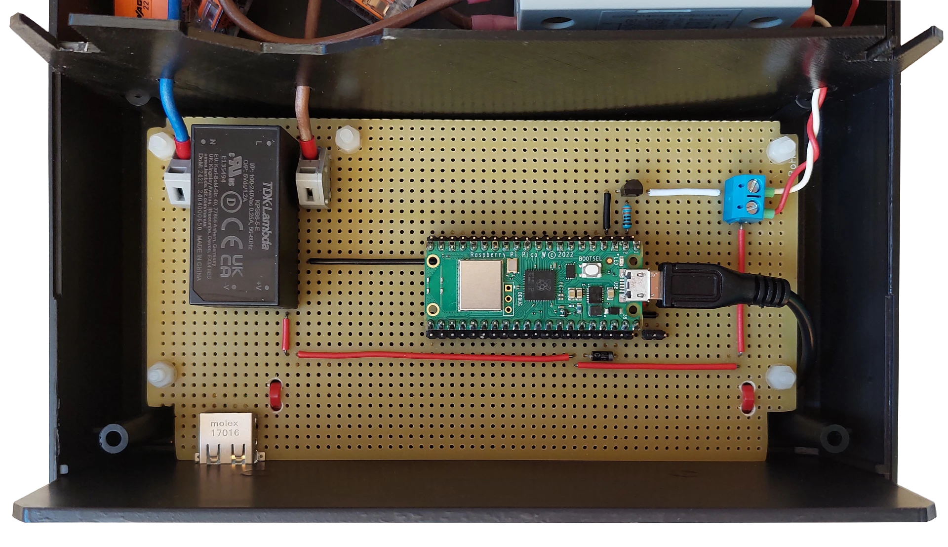
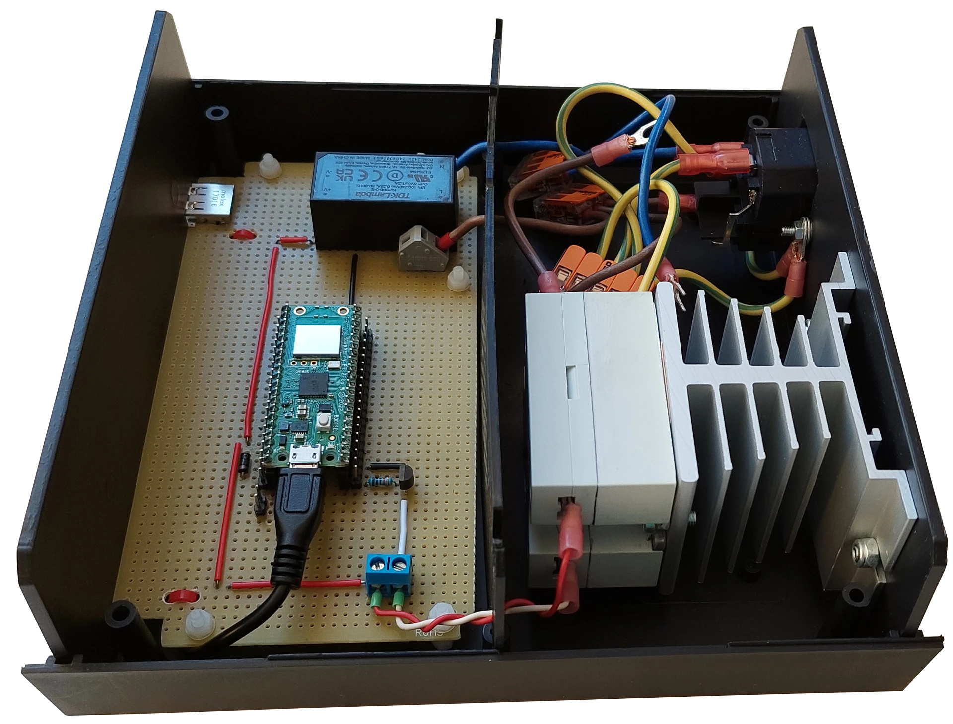
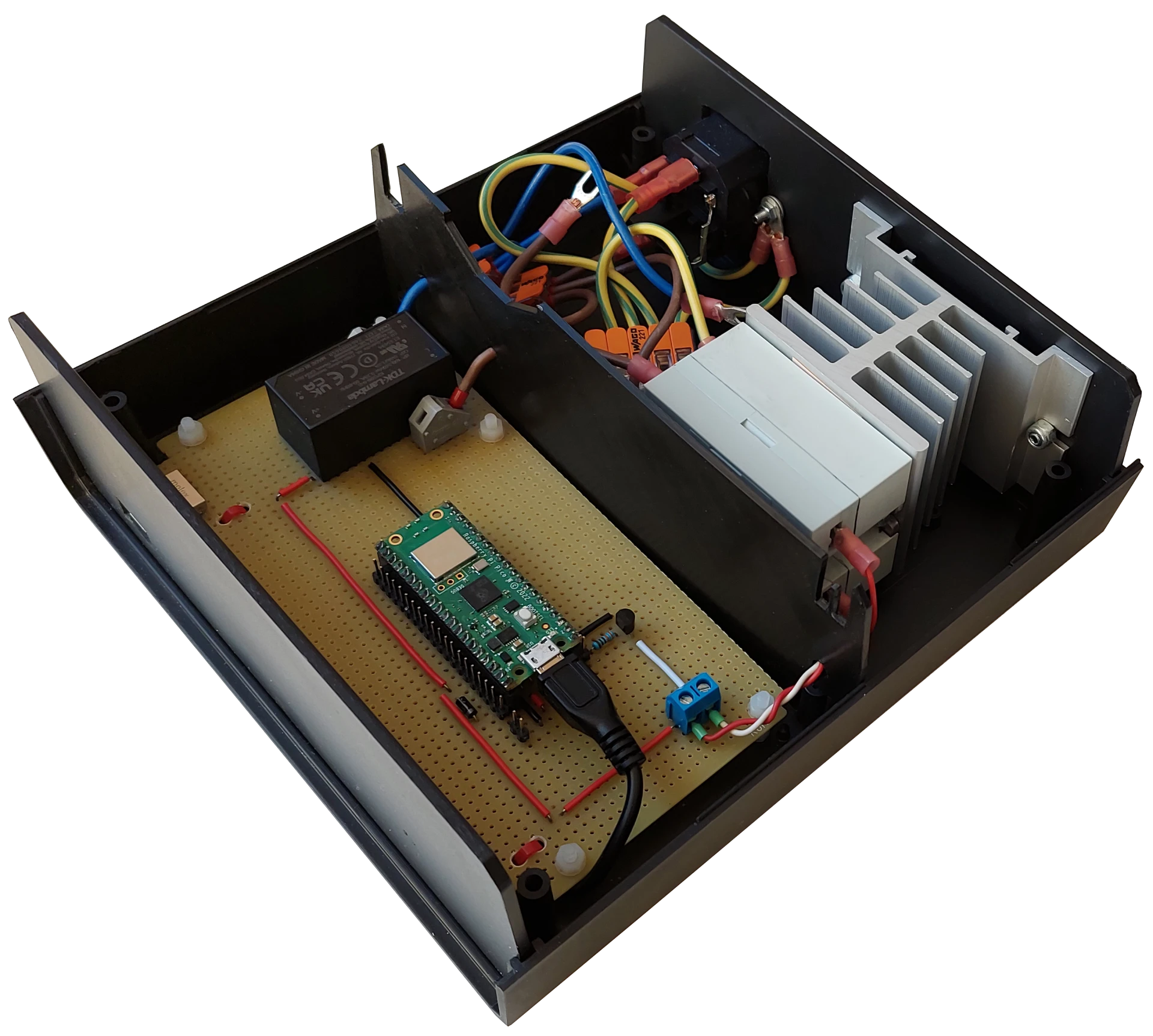
As you may have noticed in the pictures above, there are some other minor DC components; however, instead of describing them, I am including the circuit diagram so you can deduce the rest on your own.
Temperature measurement
To measure high temperatures, there are basically two options: thermocouple or thermistor. I have decided to go for the latter. I am not an expert in this field, but here are some reasons why I chose the NTC thermistor.
- Thermistors can easily be purchased separately, without a housing, which, in my opinion, may shorten the response time to temperature changes.
- They do not need any complicated circuitry, only one resistor.
- They are significantly cheaper than thermocouples (assuming you want to use reputable manufacturers' parts), even when adding the costs of heat-resistant wire and heat-resistant glue needed to make them. The more thermistor sensors you want to produce, the cheaper a single unit will cost, because the glue will last for much more than just one sensor.
- They offer good accuracy, but worse than thermocouples (at least the thermistor I bought). In the worst case, at 250 °C, the readings may be off by ± 9 °C. It is not perfect, yet not terrible.
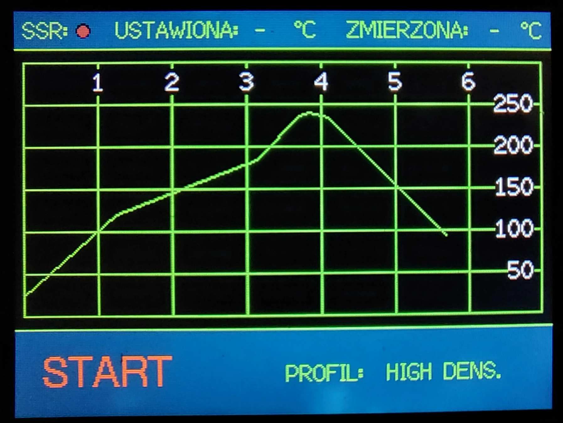
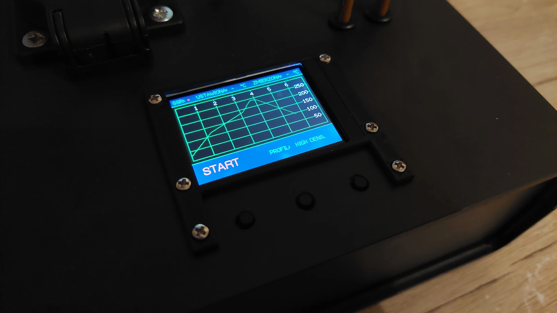
Graphical user interface
As I mentioned earlier, I have decided to design and program the GUI with the help of the TFT_eSPI library, which is one of the most popular libraries for TFT LCD displays in the C++ language. I have divided the display into three parts. The top part contains information about the SSR work status, the set temperature at a given time point, and the measured temperature. The middle section features a temperature (°C) vs. time (min) graph. On the graph, the selected soldering profile is also drawn, as well as the profile of the current soldering batch when the soldering process is running. In the last section at the bottom, I have placed the Start/Stop button and the soldering profile selection button. I am also considering adding a data collection interface in the future to send each soldering batch's data to a computer. Currently, I have added two soldering profiles for the SAC305 alloy (Sn96.5/Ag3.0/Cu0.5) soldering paste that I will be using: one profile is for low-density boards, and the second one is for high-density boards (density of the components).